Home > Products Guide > DynAmp LKCO
DynAmp LKCO
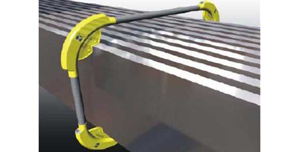
LKCO represents a significant breakthrough in high current measurement. Advanced optical technology senses the phase shift in light caused by the magnetic field from the bus current when it is routed around a current carrying bus via fiber optics.
Key Features
? Superior, rejection of external influences. Permits installation on compact and geometrically complex bus work. No need for DynAmp Bus Analysis or exact positioning to optimize performance.
? Excellent Low Current Performance thanks to true bi-directional operation and near perfect integration of the bus magnetic field.
? Extremely compact and light-weight. Designed to be “bus bar mounted”. Eliminates additional support and protection structures. Compact modular head allows installation with less than 500px of bus clearance
? Patented Closed-Loop “Full Compensation” places the entire system (light source, opto-electronics, fiber optics and even measurement outputs) under closed loop control to automatically compensate for long term changes.
Technical Overview
1) Polarized light is split into two linearly polarized light waves.
2) The two linearly polarized light waves are converted to circular polarization before traveling
around the bus, reflecting off the end of the fiber and returning along the same path.
The bus magnetic field creates an optical phase shift due to the Faraday effect. Because the two
light waves are polarized in opposite directions, the shifts are in opposite directions.
Other conditions, such as vibration, also create an optical shift but affect the two light signals in
the same direction, therefore not changing the “measurement” shift.
3) The two light waves return to the opto-electronics where phase shifts are measured for a 'raw'
measurement signal
4) Patented closed-loop full compensation accurately nulls this shift electromagnetically in the
same medium that sensed the bus current. This automatically compensates for any gain, sensitivity
and zero point change or long term drift in the entire system ( light source, opto-electronics, fiber
optics and measurement output signal ).
5) Advanced Accuracy Diagnostics (A<sub>2</sub>D) continuously monitors system operation and performance to enhance measurement confidence. A<sub>2</sub>D notifies user of specific installation problems, developing problems and faults. A<sub>2</sub>D even records events for subsequent analysis and root cause investigation and is available via digital connection.
Specifications
Input : Bus Current to +/- 600 kA full scale
Over-current 110% of F.S. measurement
Infinity without damage
Measurement Performance (applies from 10% to 110% of F.S.):
Measurement accuracy ±0.1% of measurement
Repeatability ±0.02% of measurement
Linearity ±0.1% of full scale
Measurement Outputs : Uni-directional or bi-directional
Standard :Low Level Shunt Voltage Feedback Current (5V max burden)
< 100kA 10mV / kA or 1V FS 1A FS
> 100kA 1mV / kA or 1V FS 4mA/kA (250000:1)
Optional : Low-level current 0/4…20mA full scale
High-level voltage 0 to +/- 10V FS
Frequency 0 to 10kHz full scale Digital / network ModBus or ProfiBus
Digital display Internal or remote
Mains 95…264VAC@47…63Hz or 100…264VDC
350VA w/o environmental options
Isolation ( Hi-Pot tested at 60Hz )
Head to output / chassis 6.0kVAC for 1 minute
Mains supply to output 1.5kVAC for 1 minute
Mains or Output to chassis 1.5kVAC for 1 minute
Environmental Operating Storage
Measuring Head IP65 -40o to 70oC -40o to 70oC
Compensation Module IP65 -40o to 70oC -40o to 70oC
Metering Unit IP54 -10o to 40oC* -40o to 70oC
*Metering Unit requires fan option from 30o to 40oC
or air conditioning option for over 40oC ambient, requires heater option below -10oC
Humidity (non-condensing) 0 to 85% 0 to 60%
Metering Unit to Compensation Module Cabling
DynAmp supplied cabling : 30m standard
Connectors at Metering Unit
Physical
Metering Unit 1525px w x 77 h x 54 d
Compensation Module 1100px w x 39 h x 17 d
Measurement Head Modular, sized to bus
(250px x 250px cross-sec)